Data Acquisition and Registration

DAT data acquisition and logging equipment has been developed to record parameters of special foundation activities, drilling, and geotechnical activities. All DAT products are highly specialized and ensure excellent long-term performance.

Techniques:

  • Grouting
  • Jet grouting
  • Soil mixing / Deep soil mixing
  • Vibroflotation
  • Continuous flight auger drilling
  • Conventional drilling
  • Lugeon and Lefranc tests
  • Diaphragm walls
  • Anchoring


Areas of interest:

  • Construction and maintenance of dams and tunnels
  • Construction of bridges, roads, and highways
  • Special foundations
  • Waterproofing
  • Drilling logging
  • Permeability testing

The Lugeon test is a test carried out on a section of a hole, where water is injected at a constant pressure, during a certain period of time; the value obtained (Lugeon Units) is defined as the amount of water injected in liters per minute and per meter hole at a pressure of 10 bar.

JET DAQ 2A (1 bomb):

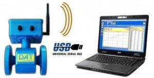
  • Direct connection to PC in real time.
  • Measurement of pressure, flow and volume parameters.
  • Displays instantaneous pressure, average flow and volume values directly on the PC monitor
  • Real-time PC monitor display of all Lugeon charts and summary reports.
  • Data logging directly to the PC

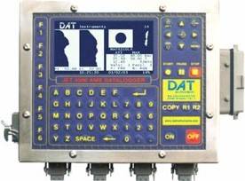
JET 4000 AME/ I (1 to 4 bombs):

  • Measurement and recording of pressure, flow and volume parameters.
  • Display, directly on the LCD datalogger, of instantaneous pressure, average flow and volume values.
  • Real-time presentation of injection graphs and summary reports.
  • Automatic stop of water injection, by the GIN method, when the maximum values of pressure and volume established or reached the maximum duration are reached.
  • Automatic restart of injection if, after stopping, the pressure drops below the pre-set values
  • Test start directly from the datalogger keyboard JET 4000 AME / I
  • Sending a project from the PC with different types of tests to avoid configuration on site.
  • Data download to PC for creation and printing of summary reports in order to obtain files for quick and easy printing of the tests carried out, as well as exporting data to Microsoft Excel.
  • Possibility of immediate data printing through the JET PRINTER 60 compressor that can be installed in the datalogger
  • Possibility of connection to PC in real time

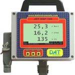
JET DSP 100 / IR (1 bomb):

  • Measurement and recording of pressure, flow and volume parameters.
  • Display with oversized digits, and directly on the LCD datalogger of instantaneous pressure, average flow and volume values.
  • Data download to PC for creation and printing of summary reports in order to obtain quick and easy information files on injections performed as well as export to Microsoft Excel
  • Possibility of connection to PC in real time.
For low pressure injections DAT Instruments provide two types of products: JET AME 4000 / up to 4 pumps, with monitoring, recording and automation functions;
  • Measurement and recording of pressure, flow and volume parameters of the grout.
  • Display, directly on the LCD datalogger, of instantaneous pressure, average flow and volume values.
  • Real-time display of injection graph and summary reports.
  • Automatic stop of the injector, through the GIN method, whenever the maximum established pressure and the maximum volume of the mixture are reached, or when it is
    maximum duration is reached. JET DSP 100 / IR, for 1 pump only with display and recording functions.
  • Measurement and recording of pressure, flow and volume parameters of the grout.
  • Display with oversized digits, and directly on the LCD datalogger, of instantaneous pressure, average flow and volume values
  • Data download to PC for creation and summary printing of reports in order to obtain quick and easy information files on injections performed as well as data export to Microsoft Excel.
The CFA technique (Continuous Augers) is a pile injection method. The ground is drilled with a continuous auger and then injected with cement through the same auger. Once the injection is completed, reinforcement is introduced into the hole.
Display, directly on the LCD datalogger, of instantaneous and average recorded parameters, graphs related to depth and summary data.
Automatic startup of the equipment at the beginning of the registration; automatic stop when reaching the desired depth; automatic management of the rise of the poles (on/off control, optional: proportional). Automatic recognition of the rod change operation. Automatic suspension of registration
Data download to PC in order to process files, export and detailed reports.
Measurement and recording of the following selectable parameters (by sensors suitable for both the drilling and the rod removal operation)
  • Drilling depth (JET DEPTH)
  • Drilling advance speed (JET DEPTH)
  • Torque (JET TORQ)
  • Rotation speed / Sticks (JET ROT)
  • Tower Inclination (X and Y axis) (JET INCL XY)
  • Cement pressure (JET PRESS)
  • Cement flow rate and volume (JET FLOW)
  • Possibility of regulating the rise time of the poles
  • Injected pile length
  • Date (Start and end of work)
  • Input for GPS receiver
The Jet Grouting technique consists of injecting cement grout at high pressure. The Jet-2 version consists of injecting air and cement and allows the construction of large diameter piles. The Jet-3 version consists of the simultaneous injection of air, water and cement.
Display, directly on the LCD datalogger, of the instantaneous and average parameters recorded as well as the graphic record relative to the depth and summary data.
Automatic start of the equipment at the beginning of the log, automatic stop when reaching the depth, automatic management of the phased time of ascent of the poles.
Automatic recognition of the rod change operation
Automatic registration suspension.
Data download to PC for file processing, export and detailed reporting.
Measurement and recording of the following parameters (by appropriate sensors both during drilling and when removing the rods):
  • Drilling depth (JET DEPTH)
  • Load / Weight on the drill string (JET FORCE)
  • Feedrate / Drilling feedrate (JET DEPTH)
  • Torque (JET TORQ)
  • Rotation speed / Sticks (JET ROT)
  • Tower Inclination (X and Y Axis) (JET INCL XY)
  • Cement pressure, flow rate and volume
  • Water pressure, flow rate and volume
  • air pressure
  • Phased time of the ascent of the poles
  • Injected column length
  • Date and times of drilling / Injection and duration
  • Relative energy of the terrain
  • Input for GPS receiver
Real-time parameter logging. It is possible to analyze different drilling parameters and their correlation with the mechanical characteristics of the terrain.
The diagram of the drilling parameters allows highlighting the levels with different characteristics and making stratigraphic correlations of the terrain.
Display, directly on the LCD datalogger, of instantaneous and average recorded parameters, depth graphs and summary data.
Automatic start of the equipment at the beginning of the log, automatic stop when reaching the desired depth.
Automatic recognition of the rod change operation. Automatic suspension of registration
Data download to PC in order to process files, export and detailed reports.
Measurement and recording of the following selectable parameters: · Drilling depth (JET DEPTH)
  • Load / Weight on the drill string (JET FORCE)
  • Feed / Feed speed (JET DEPTH)
  • Torque (JET TORQ)
  • Pole rotation speed (JET ROT)
  • Tower Inclination (X and Y axis) (JET INCL XY)
  • Water pressure (JET PRESS)
  • Water flow and volume (JET FLOW)
  • Date, drilling times and duration
  • Relative energy of the terrain
  • Input for GPS receiver
The soil mixing technique consists of injecting cement during drilling and in the injection phase at low pressure.
There are two types of operation: superficial and deep (soil mixing in depth).
Display, directly on the LCD datalogger, of the instantaneous and average parameters recorded and the graphs related to depth and summary data.
Automatic startup of the equipment at the beginning of the registration; automatic stop when reaching the desired depth; automatic management of the rise of the poles (on/off control calculated on volume / footage)
Automatic recognition of the rod change operation. Automatic registration suspension.
Data download to PC in order to process files, export and detailed reports.
Measurement and recording of the following parameters (by appropriate sensors for lowering and removing the rods): · Drilling depth (JET DEPTH)
  • Load / Weight on the column (JET FORCE)
  • Advance / Pole forward speed (JET DEPTH)
  • Torque (JET TORQ)
  • Rotation speed / Sticks (JET ROT)
  • Tower Inclination (X and Y axis) (JET INCL XY)
  • Cement pressure (JET PRESS)
  • Cement flow rate and volume (JET FLOW / E)
  • Liters / meters injected
  • Length of treatment
  • Date (Start and end of work) Duration
  • Input for GPS receiver
Molded walls must be executed in order to obtain a work according to the project. Verticality and rotation must obey a careful work plan to guarantee the impermeability of the joints.
Datalogger JET DSP 100/ D with display, on an oversized monitor, and recording in internal memory of the following parameters:
  • Depth (m, with 1 cm resolution)
  • Tilt, on X and Y axis, relative to the vertical (with 0.1° resolution)
  • Grab rotation, about Z axis, (with 1° resolution)
  • Deviation, X and Y axis, from the vertical (with 1 cm resolution)
The data is acquired by sensors installed in the excavation equipment. The inclination sensor can be connected to the datalogger by cable or via radio. The JET DSP 100 / D can record the excavation data as a function of depth. In the course of the necessary blows for the execution of the molded wall, the individual data of each blow are recorded. The last hit data is also recorded in order to analyze the excavation on the PC when returning to the office. The datalogger can be connected via PC. In this way, it is possible to calibrate the sensors, introduce data acquisition parameters and display values in large-scale graphs.

The Vibrofloating technique uses a vibrating torpedo that penetrates the ground.

This is compacted by virtue of this vibratory action. Gravel-like materials are accumulated in a free space produced by vibration. These materials will increase the solidity of the ground.

Display, directly on the LCD dattaloger, of the instantaneous and average parameters recorded, the graphs related to the depth and the summary data.

Data download to PC in order to process files, export and detailed reports.

Measurement and recording of the following parameters (by appropriate sensors for the descent and withdrawal movement of the hammer):

  • Depth of treatment (JET DEPTH)
  • Volume of added gravel (number of jaws
  • Current absorbed by the electric hammer

or

  • Hydraulic hammer pressure
  • Duration of treatment
  • Date, (start and end of work), duration
  • Input for GPS receiver